An optimist will tell you the glass is half-full; the pessimist, half-empty; and the engineer will tell you the glass is twice the size it needs to be. – Oscar Wilde
Thursday, September 06, 2012
Electropong is going to change everything
I've been playing beer pong for the better part of 20 years. During that time, the tried and true setup and rules of the game really haven't changed that much. Why mess with a classic. Sure there have been many variations on the table used, certain house rules that one needs to entertain, and everyone has there own style of toss; but the core essence of the game has stood the test of time. I'm looking to shake that up a bit. Introducing Electropong!
Feel like playing beer pong during the winter months but your brew freezes before you get a chance to throw. Wanna play inside but your significant other will raise hell if you get beer on the new carpet. Tired of wondering what germs you're passing around drinking out of the same cups everyone else is. Electropong may be just the game you're looking for.
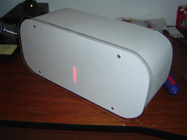
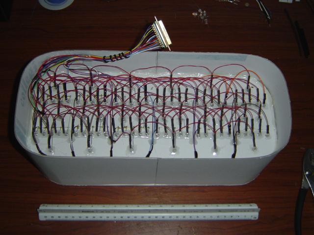
Alright, I'm not here to give you the sales pitch, I just thought it would be neat to build an electronic beer pong game. It's very much like the electronic darts game machine you might find at a bar. Two teams play on one unit and hit the "swap team" button to cycle their turn. The color of the cups and the LED display keep track of which team is currently throwing. Each of the six cups has a RGB LED embedded inside and a hole at the bottom so a 40mm ping pong ball can pass through it. Under the cup base, the enclosure houses six IR interrupters, a 9V AC/DC power supply, a custom LED driver board (recycled from an old project) and a custom PCB that controls everything. In addition, there are three arcade style buttons on the front face that also have RGB LED's lighting them up. The display in the back is an off the shelf Betabrite scrolling LED matrix and above that are two mini beacons I got from Woot! The control board has a PIC18F6622 micro-controller that reads in all the IR interrupter inputs, talks to the LED matrix display, does PWM for the LED drivers, toggles the beacons and keeps track of the game play. I think that pretty much sums up the hardware section.
The real magic happens in the software. You can play games on Electropong that wouldn't be possible with the traditional setup. For instance, a popular game with my guests has been "king of the hill" where teams go head to head on the same board and try to be the first to light up three cups of their color. This game tends to go faster than regular pong and is a good fit for people who want to play a quick game and get back to the party. I'd still like to add one or two more games so if anyone has an idea, please leave a comment.
The construction of this game definitely wasn't without it's challenges. An un-tethered Solo Cup with about two ounces of beer in it sitting on a wet surface has some mechanical dampening properties that are difficult to simulate. At first, the cups on Electropong were rigidly fastened to the base with four screws. This caused the ping pong balls thrown at them to ricochet off dramatically. Turns out, the necessary shock absorption system was built right into the cups themselves. About a quarter inch of the outside diameter of the cup base sits squarely on the ground while the rest of the base is raised about an eighth inch. The screws attaching the cups were pressing this raised portion down so backing the screws out a little allowed the cups freedom to pivot a bit. However, in doing so, the imprecise holes I made in the cups allowed too much movement and they ended up not lining up correctly. I fixed this by laser cutting a donut shaped spacer that fits in between the screw heads and the bottom of the cup. This locked the cup in place and still allowed it to pivot, effectively dampening the force of the ball against the cup. The second significant challenge was reigning in the size of the unit, especially the height. If the cups were offset too much from the table top, they would look awkward and the game-play would suffer. However, I still needed to concoct a ball return system. I ended up cutting away some of the base and putting the ball return ramp in its place. Had to go back to my junior high school trig skills to figure out the angles. I was very proud of myself.
Purists will object to certain aspects of the game that have been taken away like the rush of having to drink from a selected cup but I think I have made up for that with the additional games and the spectacle of lights. I don't want to compete with the traditional game, I want to add to it. But hey, my party guests really seem to like it. I guess that's what matters most.
Oh, one more thing. There is a reason the cups are black. Aside from the obvious styling advantage, I needed to go with black so the light from the LED wouldn't bleed out through the cup. I initially wanted red cups but any hint of red light would make them glow like a lantern. And I think black makes the game look cooler, what do you think?
Monday, June 04, 2012
Networked Betabrite and a better party music solution
![]() |
| Home-brew Ethernet to RS-232 converter |
For a recent party, I was looking for a better solution to my current audio setup and happened across a reconditioned Apple Airport Express on the web. While it has many features, I primarily wanted it for streaming music via iTunes on the ol laptop to my stereo receiver over the home network. With WiFi enabled I can locate the computer anywhere in the house I want. And I can control the playlist with the remote app on my iPhone. Got it, hooked it up, and everything worked great... but something was missing.
For the same party, I was planning to set up my Betabrite scrolling LED sign to display a few generic messages such as the contents of the kegerator and a couple birthday wishes. I quickly realized how boring the repetition would be. You really must have continual content updates to keep the public's attention. Hmmm, maybe I should heed my own advice with this blog ;) I've seen other people scroll twitter updates and directed text messages to their betabrites but I don't currently have their programming chops so I opted to gobble up some local data.
I thought I would be neat to combo the new sound system with the display and scroll the currently playing song title and artist on the betabrite. I had two weeks before the party, plenty of time right? There were challenges.
Challenge number one, hardware. In a nutshell, I needed an Ethernet to serial (RS-232) converter so I could connect the Betabrite directly to my router. You can buy a quality unit for around a hundred dollars but a quick trip to the spare parts bin yielded a bounty that would get me most of the way there. The heavy lifting is done with a Lantronix XPORT Embedded Ethernet Device Server. I'm a big fan of these little guys. It has many features but for this project I only utilized its UART (serial) output. On the PC side, you can use vendor provided software to create a virtual com port eliminating the need to fool with setting up a socket connection. The XPORT outputs TTL level signals but the betabrite sign requires +/-15V (RS-232) so I needed to gin up a proto board with a level shifter on it. As luck would have it, I made such a board for a previous project. After tossing in a 3.3V linear regulator to power the XPORT, the hardware was complete.
Challenge number two, software. This was by no means trivial, I dabble in the medium at best. From a past project I already had a little C++ code that talks to the serial port so I decided to start there. The next logical steps were to gather up relevant information from iTunes, format said info, and write it out to the Betabrite. On a Mac, interacting with iTunes is native but Windows plays with iTunes a little differently. It uses the COM object interface to handle the data exchange. Thank goodness for Google and online example code. The only real trick was setting up the Visual C++ dependencies correctly and getting all the various updates and whatnot working. Looking through forums for semi-useful and somewhat relevant information is tedious. I'll provide the code and environment setup instructions upon request. Writing to the Betabrite also proved to be a bit tricky. I had the programming guide along with some sample scripts but I still had to snoop the serial data from the vendor software to figure out the ins and outs of the protocol. You can never underestimate the importance of a good technical writer.
Having the Betabrite display update with the currently playing song turned out to be a hit with the party goers. I'll have to make it permanent fixture for future gatherings. Maybe I can even get some tweets up there next time.
Monday, June 27, 2011
Fun with sensors
A couple years ago I put together a kegerator and while draft beer at home is great, the project never felt complete. The system performed well but there were a couple of issues that would crop up from time to time. Mainly, figuring out how much beer was left in the fridge consisted of opening the door and pawing at the keg. Besides this being unscientific, the act of opening the door would let all the cold air out and the compressor would have to crank to keep up. And speaking of temperature, it would be nice to have a good idea of how cold the keg is getting.
![]() |
| Scale for Fuel Gauge Measurement |
I thought the temp sensor was a no-brainer but it turned out to be a little tricky. Idealy, I'd like to know the actual temp of the beer but since the keg is a sealed container, that is impossible. The next best thing would have been to simulate the keg with an approximate thermal mass and sense the temperature of that but I didn't have the space. That and I had already decided to be lazy and use a board mounted digital temperature sensor instead. Couple drawbacks with that idea though. Since it is soldered to the sensor control board, thermal coupling to said board is an issue and placement in the fridge cavity is somewhat limited. And to get a reading that actually means something, placement is critical. Turns out that placing the board right under the fridge chill plate gave me some pretty accurate results when compared to a mercury thermometer. And it was a good indication of what the fridge's themocouple was reading since the compressor cycle and my temperature readings tracked almost exactly in phase. That's important because one day I may want to take over control of that cycle for tighter temperature regulation.
So now I want to display all the good data I'm getting. I used cast iron pipe for my keg riser so I felt it was necessary to stick to that theme and go a little industrial with my display options. After an exhaustive search online, I finally came across the perfect meter housing from an early model Chevy. On ebay of course. It was pretty beat up when I first got it with splotchy paint and some pretty rough edges. I was originally going to sand and paint the thing but ended up trying my hand at paint stripping instead. Peep the before and after.
| Meter Housing Before and After |
![]() |
| Modified 0-5 Volt Analog Meter |
I made four boards for this project. They are mostly unpopulated in the picture to the left because I like to test out the micro first before I finish them up. I'm weird that way. The board at the bottom went in the keg fridge and has circuitry to read all the sensors. It also manipulates the data into an easily read format for the display control board in the middle. That board drives the Tri-Color LED drivers and does a couple D/A conversion to drive the analog meters. The board on the upper left will eventually house a relay to control the compressor cycle and the board right next to that is a RS232 level shifter so I can divert the TTL level UART signal intended for the display board to a PC for debug purposes. Being able to save the sensor data off to a PC was also helpful when developing my display averaging algorithms.
Wednesday, January 05, 2011
Collaboration
The shelves are 16" cubed, built into the wall, made out of sheet rock and painted white. I wanted to light'em up and I knew just what to do. The trick was finding a RGB LED worthy of the job. DealExtreme is a tad sketchy and based out of China but pretty much my only bet for 3W RGB's at anything close to a reasonable price.
The construction of the circuit board was pretty straight forward with only one notable addition. Along with the 3.3V power supply, LED driver chips (CAT4103), and obligatory PIC micro-controller (PIC18F2510), I used a Lantronix XPORT Ethernet to Serial module to accept commands from any network attached device. It was agreed that I would leave all the software design up to the neighbors. After all, they are the professionals. My board reads in a command packet, writes the LED intensity registers and creates a pulse width modulated (PWM) signal to update the RGB LED drivers. When I design any board, I like to make it as versatile as possible in the event I decide to add any features after the fact. There are only 7 shelves but I built the board with 12 drivers just in case. Two boards can also be stacked to drive a total of 24 RGB LED's as you can see in the picture below. Turns out we'd need all 24 but I'll tell you more about that later.
So I finished the hardware, installed my custom firmware and performed the least amount of testing it took to convince myself that there was a chance it could work. My neighbor Mark was designing his visualization software in parallel with only a loose discussion of what the command packet should look like to go by. The idea was to get together once each part was done and spend way too much time debugging the inevitable problems. That is until it worked right out of the gate. Sometimes the lighting of a single indicator LED can stir up a bevy of emotions in the average geek... imagine the lighting of an entire bank of shelves. I'll have to admit, Mark's software is pretty impressive. My favorite part is the connection with iTunes. While a song is playing, it gathers frequency information on the fly and displays it on the shelves in a variety of ways. Check out the video at the bottom to get a better idea of what I'm talking about.
If working solo, I may have called it a project and moved on. However, the neighbors had a vision and a suspicion that I wouldn't leave them hanging. They installed 20 overhead can lights in the drop ceiling and four wall sconces in the theater section. 24 extra LED's huh, yikes!
The hardware wasn't a big deal cause it was pretty much done already. LED installation and firmware development... Now that was a bit tricky. The room lighting was already wired up for 120Vac so the LED's had to be installed in such a way that proper light diffusion was achieved within the housing and the housing itself wasn't altered in a severe way. The blue socket protection cap provided as close to a perfect solution as we were going to get. The cap was meant to fit snugly into the existing light socket so I just mounted the LED to that and attached a strain relief on the side. Neat and tidy.
So for the ceiling and walls, that is 24 RGB LED's which makes 72 (24x3) discrete sources of light. To drive each LED at different intensity levels, I switch them on an off at a set frequency and vary the percent at which each LED is on during a cycle period. If it's on half the time, it appears to be half as bright as a LED that is continually shining. For this project I chose a refresh frequency of 60Hz with 32 levels of intensity. Therefore, I have to update each of the 72 LED's 32 times every 1/60th of a second. In other words, I have 520 microseconds to update 72 LED's. With a 16MHz oscillator, the instruction cycle on my micro-controller is 250nS. So, the update period divided by the instruction cycle time divided by the number of LEDs gives me a total of 26 instructions to preform everything needed to decide whether a given LED needs to be on or off. I ended up needing 22. Just squeaked it in there after a bunch of tweaking and a little luck.
Tuesday, July 27, 2010
This card box runs firmware...
And lights up of course. One minor detail in the vast expanse of wedding preparation is the acquisition of some sort of receptacle to house cards or envelopes that may get lost in the shuffle of larger items on the gift table. I suggested to my soon to be wife that I could handle the task of building such a thing and she happily accepted knowing full well what the outcome would be. I appreciate her willingness to support my hobbies and obsessions. And so it began. Don't forget to watch the video at the end, not bad for iPhone video huh.
Among the design considerations I mulled over, I felt color scheme and an interactive element took precedence over the rest. Sure, the box contains a few old tricks but incorporates enough new (to me) tech to satisfy my desire for an original product. Most of the time my designs are influenced greatly by the available materials and tools at my disposal. This project was no exception. How hard is it to find a lightweight and inexpensive yet sturdy cylindrical box big enough to hold approximately 70 large envelopes? Too hard, I basically had to make my own out of two hat boxes, tape, some brown utility paper and a lot of glue.
Let's start with the new stuff. Our wedding colors were purple and green so the box had to match the particular shades we selected as close as possible. Probably could have done it with paint but decided fabric was better for a few reasons. On the top of that list, Deb got me a sewing machine for my birthday so I was itching to do more than hems and patch jobs with it. Plus, fabric does a great job of hiding blemishes and rough edges. Turns out there were plenty from the aforementioned hat box mod. And the fabric store had plenty of colors and patterns to pick from. A little too many perhaps, it was hard to decide.
Since people were going to be interacting with the box by putting cards into it, I thought it would be a good idea to provide some feedback. Oddly, I've never worked with photointerruptors before but it was obviously the perfect way of sensing something entering the box. When a card blocks the infrared light between transmitter and receiver, a signal is send to the microcontroller. I thought it appropriate that the micro respond by flashing some green lights.
The focal point of the card box is of course the etched plexi with our logo on it. As you can see from the previous posts, we kind of liked it. I etched the plastic in the same manner as I have in the past but finished it in a different way by bending it to match the contour of the round box. I think it ties in quite nicely.
This was a fun project. I learned a few things in the process and everyone at the wedding seemed to get a kick out of it. I guess it's my silly way of saying thank you for all the gifts.
Sunday, August 16, 2009
Proposal
There are many things to consider when proposing to your girlfriend. Some of more importance than others. I'd guess the ring delivery system is probably pretty low on most people's priority lists. But apparently not on mine. I wanted to find a way to make this proposal unique, make it personal and memorable. Short of implanting a light source in the ring, making an over the top jewelry box to house the ring seemed like the right thing to do. You'll want to check out the video for full effect. Oh BTW, she said yes!
Monday, February 23, 2009
Framed on V-Day
This project took me way more time than I initially imagined. Good thing I started it more than a month before Valentines Day. Choosing the digiframe was not a trivial task. Most of the frames I found where either undersized for my taste or large, expensive and wide screen. I guess the wide aspect screen is good for HD video resolutions but I'd wager most people are going to go primarily with digitized photos which are almost entirely produced with a 4:3 resolution aspect ratio. After a pretty good search, I found an adequate candidate in an 8" Matsunichi model. I took a bit of a gamble with a non name brand selection but that ended up working in my favor since the flimsy construction made ripping it apart pretty easy. And the screen turned out to be just as bright as the reviews said it would... Bonus.
Check this out, I used a friggin laser to cut the letters out of the front bezel. Would have been a lot cooler if not for the smell of burnt plastic. A friggin laser! The rest of the outer casing came together with some high strength plastic glue and screws. And then came the programming. I hacked together some of the ugliest code you can imagine. I really need some training in proper coding techniques. Yikes. But the end result looks pretty good so I'm happy. Though I think during "Randy Jackson presents America's Best Dance Crew" she likes the TV just a little bit more.
Tuesday, August 26, 2008
Turbo Boost
I recently recreated my Knight Rider Belt for a trip out to the State Theater to see the Legwarmers. The original belt died after the party for which is was built. Not too surprising really, it was sort of a last minute thing and the construction wasn't that solid. Normally I would have called it a project and moved on but I was never really happy with the way the light diffusion worked in the original so I instituted a few new tricks and put together a far superior product.
Tuesday, July 08, 2008
One Point Twenty One Jiggawatts!
Ok, so i had way too much time on my hands so I decided to recreate the Flux Capacitor from Back To The Future. Actually I needed a costume for our annual 80's party so put one Flux Capacitor on top of some shiny silver clothing and wham! You've got yourself a Delorian costume. In theory at least. I had some last second power issues so I couldn't pull it together. Stupid regulator not running at 4.6Vdc. But it works now so it makes a pretty interesting decoration when I'm not using it to travel in time. And if you're wondering, we still don't have rocket packs or flying cars in 20 years. So so lame.
This thing really wasn't too hard to pull together. The casing is just a outdoor panel box which I chopped to decrease it's overall depth to about 3 inches. I made the front window with some plexi and rubber molding. I really like how that turned out. The rest is a bunch of amber LED's, a role of clear tubing, some paint, three right-angle RCA housings, some yellow wire and a few 1" PVC caps. Personally I think it looks better than the real thing. But I'm a proud geek so that's not too surprising.
Monday, February 05, 2007
Arcade Displaya Hater
At the moment, the display only cycles through a pre-determined sequence of words and symbols but it's connected to the arcade's PC via the serial port so it'll eventually (sooner than later) display high scores and game titles. Neat huh? I dropped off some design elements halfway through construction so I think I would have approached this differently had they not been there at the beginning. Being that I was initially constrained by size requirements, the character spacing is a little closer than general standard practice and I didn't utilize all of the LED driver chip's available characters. But I'm still pretty happy with the way it turned out so I can't complain too much. Wanna see a video?
Tuesday, January 23, 2007
Le signe est fait. Translation... "sure took me long enough."
The "Bar Sign" project is finally complete. I think my sister liked it although I did see some gaps in her enthusiasm during the unveiling. I believe they were failed attempts at comprehending my fascination with LED's. She was right to be confused, a tiny blinking light can only giddify the most stout of geeks. I hope she enjoys looking at it as much as I enjoyed building it.
Speaking of construction, allow me to front you some details. The black wooden shadow box frame measures in at around 20"x8" and holds two pieces of hand etched Plexiglas panes illuminated by six tri-colored (RGB) high intensity LED's. Quite a mouthful huh? That's not the fun part. To drive all the the color combinations possible, I used a Microchip PIC16F676 microcontroller and a Maxim MAX6957 LED driver to do all my dirty work. I'm still trying to decide why I wrote the firmware in assembly. Sometimes those things harder to do aren't always worth doing.
Want some theory? I'll let Wikipedia handle the bulk of the work for me. In a nutshell, I vary the intensity of red, green, and blue light to create any color I want. I direct that light through the side of each pane of Plexiglas and it escapes only where I have etched it. I didn't go too crazy with the lighting programs. I only wrote five and they can be cycled through by pushing a button on the side of the frame. I also included a control knob so you can pick your own color if the appropriate program is selected. But enough of this talk, here are some pictures and a video.
Friday, November 03, 2006
Plexiglas, the other clear synthetic polymer of methyl methacrylate.

I wouldn't consider myself a controlling, type "A" personality, but I do push plexi around quite a bit. I've cooked it, bent it, drilled through it, sanded it, polished it, cut it, cracked it, and scowled in its general direction quite a few times. And I'm not done yet. I have the technology, means, time, and minimal artistic ability to etch me some plexi so that's what I'm gonna do.
My sister has a shelving unit with a few select spirits adorning it so I thought I'd etch her a nice sign so no one confuses it as anything less than a full fledged drink barn.
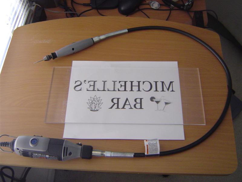
After a few internet searches, I determined a good plan of attack for the project. First thing I did was throw together some fontage and a couple clipart images. When I was pleased with the design, I flipped it and printed it. Oddly enough, that turned out the be the hardest part of the project. The etching was a breeze. It wasn't so much me as it was the Dremel tool. It's good. The trick is to hold the rotary tool firmly enough so as to avoid marking outside of the lines but gentle enough to allow for finer details. Not so easy when you're working at 5000 rpm's. There is more work to be done though. To make the etching really pop, I'm gonna light the thing up with some RGB LED's. 12,000 mcd's is a little overkill don't you think. Yeah me too... 12K it is then. I already have the color code drivers written for my fav PIC micro so all I have to do is solder up some components and make a cool frame. Don't know how the frame should look just yet but I'm sure I'll think of something. Updates to follow.
Wednesday, August 23, 2006
I'm an adult, I assure you.
I've been thinking about making one of these for a few years now but it wasn't until my neighbor Mark put one together that the wheels really started turning for me. His machine kept with the traditional size and look of 80's arcade machines but I knew I wanted to break from that a little. I wanted to go minimal with the thing. Seems to be the running trend with me these days. Initially I contemplated using fiberglass and wire mesh for the shell. I thought some nice curved edges and a smooth fluid finish would look appealing but if you've ever worked with that stuff in large doses, you can probably figure out why I shied away. I went with 3/4" fiberboard instead but it didn't make things much easier. I used an LCD monitor to shrink the top depth to about 7 inches. It appears very svelte from the side. It gets a little thicker at the bottom so the PC and subwoofer can have a place to live. The one real omission is a coin door. It may make it on there one day but I really don't feel like spending the money for one and why should I have to carry around quarters in my own house.
I think I enjoyed making it more than I enjoy playing it. It really is a great hobby because there is still so much more left to do. The high score display is almost finished, as you've probably already read about, and I hope to have the automatically rotating monitor function completed shortly after. And then there are more lights. You can never have too much lighting.
I'm still a kid at heart and it's kind of comforting to find out that at least one thing hasn't changed about me. I am still terrible at playing video games. It's a good thing I like making them.
Thursday, August 17, 2006
Arcade Display - Making Progress

My Arcade Display project is almost complete. Actually, It'd be done already if someone didn't forget to add some critical parts to my last Digikey order. It's not important who so I won't mention it here. I was having trouble finding the perfect diffusion layer but alas, a quick walk down to my local Staples store produced the material I was looking for. I needed a substance that was thick enough to hide unlit segments yet transparent enough to allow a good amount of light through. A couple of ordinary legal sized sheets of paper "borrowed" from the copy machine worked out to my liking. You can see the results in the picture above. Clean design, huh? It really looks cool when whole words start scrolling across it. Curious, why didn't I take a picture of that. Check out my previous post to see what it looks like without the paper and plexi.

Oh, and check out the wiring job. It's like I've done this before or something. And I saved around $200 making the jumpers myself. I'm sure I'll regain the use of my fingers and eyesight any day now. How am I writing this post you ask... smell and taste. I play pinball the same way.
So, what's next. When my RS232 level converted arrives, I'm gonna connect this baby up to the Arcade's PC and rock some old fashion serial communication. The goal is to display game names and high scores when playing MAME and artist/song names when playing music. I'll have to dust off my Visual C++ skillz for that. Stay tuned for updates.
Wednesday, June 28, 2006
Arcade Display Project - Retro Yet Modern
I constructed an arcade machine a few months back and while I enjoy it just the way it is in all it's arcade goodness I realize that nothing is truely finished in my world. How would the average passerby be made to know the shear ineptitude of my Pacman skill. I'll tell ya, A homemade 6 character 14-segment display my man. Why not 7 characters you ask, cause if you break a million on any game you'll be asked to leave... seriously, get out. I figure a 4"x12" display hoisted above the arcade will get people's attention. And the thing displays uppercase letters as well. Sprinkle in a touch of embittered A.I. and my arade machine will be barking out orders to its subservient users in no time. I still have to wire up 84 LED's , find some frosted glass and write me some control software but I think it's well on it's way to being half done. Updates to follow.